Abstract: This paper introduces the welding materials, welding methods, joint structures, and welding procedures used in the fabrication of fully welded ball valve bodies for long-distance pipelines. It also discusses the optimization and verification of welding materials, structural designs, and process parameters through a series of relevant experiments.
Valves are essential control components in long-distance oil and gas pipelines, used for gathering, distribution, and flow regulation. They also enable station circulation, equipment connection, tank drainage, station bypasses, and pig launching and receiving operations. Valves not only ensure the safe operation of the pipeline but also serve as key process equipment for automation and operational scheduling in pipeline transport. Among all types of valves used in long-distance pipelines, ball valves are the most commonly applied. In major national pipeline projects, the mainline shut-off valves typically use imported, large-diameter, fully welded ball valves, which are required to have a service life of 30 years or more. This article primarily summarizes the welding materials, welding methods, joint structures, welding procedures, and related tests associated with the fabrication of fully welded ball valve bodies.
Valve bodies are typically made of carbon steel or low-alloy steel, such as ASTM A105, A694, A350, and A516. The chemical composition of these materials plays a critical role in preventing cracking during welding. During the welding process, impurities such as sulfur (S) and phosphorus (P) in the weld metal can form low-melting-point eutectics during solidification, increasing the risk of crack formation. Among these, sulfur has the most significant influence on the formation of solidification cracks, although its effect depends on the presence of other elements in the steel.
For instance, manganese (Mn) can combine with sulfur to form manganese sulfide (MnS), which helps remove free sulfur and mitigates its harmful effects. Mn also improves the shape, distribution, and properties of sulfide inclusions. Therefore, to prevent solidification cracks, specific requirements are imposed on the Mn/S ratio in the weld seam metal. This Mn/S ratio is beneficial for reducing the risk of solidification cracks, and it is also influenced by the carbon (C) content. The higher the carbon content, the greater the required Mn/S ratio. Additionally, excessive silicon nitride (SiN) impurities can exacerbate the harmful effects of sulfur. As such, strict control over the chemical composition of valve body materials during procurement, and the establishment of relevant material specifications are effective measures to minimize the risk of solidification cracks during valve body welding.
Welding wire is primarily used as a filler metal to add alloying elements to the weld seam. Its chemical composition and physical properties significantly affect the stability, performance, and quality of the welded joint, as well as welding productivity. The selection of welding wire is mainly based on the material of the valve body. For commonly used valve body materials, typical welding wires include carbon steel wire (such as H08MnA) and low-alloy steel wire (such as H10Mn2). Additionally, the diameter of the welding wire greatly influences the weld seam shape. When welding current, arc voltage, and welding speed remain constant, weld penetration is inversely proportional to the wire diameter, while weld seam width is directly proportional. For fully welded ball valve bodies, submerged arc automatic welding is typically used, and the welding wire diameter generally ranges from 2.5 mm to 6 mm.
During the welding process, flux serves to shield the weld seam metal from atmospheric contamination, prevent oxidation, and participate in the metallurgical reactions within the molten pool. Once the welding wire is selected, the matching flux has a direct impact on the weld seam metal’s mechanical properties (especially ductility and low-temperature toughness), resistance to cracking, occurrence of welding defects, and overall welding efficiency. Therefore, the flux must possess good metallurgical and processing properties. Its particle size should meet the following requirements: for standard flux, the particle size should be 0.45–2.50 mm, with particles smaller than 0.45 mm accounting for no more than 5%, and particles larger than 2.50 mm no more than 2%. For fine-particle flux, the particle size should be 0.28–1.425 mm, with particles smaller than 0.28 mm not exceeding 5%, and particles larger than 1.425 mm not exceeding 2%.
In addition, the moisture content W(H₂O) should be ≤ 0.10%, mechanical inclusions should not exceed W(impurities) 0.30%, sulfur content W(S) should be ≤ 0.060%, and phosphorus content W(P) should be ≤ 0.080%. Depending on the selected welding wire and valve body material, the flux is usually chosen from high-silicon fused fluxes or high-basicity agglomerated fluxes.
The valve body is welded using submerged arc automatic welding, with air or forced-air cooling. The wall thickness of a forged steel valve body is typically between 40 and 50 mm. Narrow-gap groove submerged arc welding is recommended. The root gap of the groove ranges from 8 to 35 mm, with a groove angle of 1° to 7°. Each weld seam layer generally consists of 1 to 3 passes, and a process backing strip is often used for root welding. To ensure the filler wire reaches the bottom of the narrow groove, a specially designed narrow welding nozzle is required for insertion into the groove. The downward extension length of the welding wire is typically 45 to 75 mm to achieve a higher deposition rate. A special fine-particle flux is used during welding, which must offer good slag removal properties to meet the high strength and toughness requirements of the weld seam metal. To ensure that the welding wire and arc remain correctly positioned within the deep and narrow groove, automatic tracking control must be employed when necessary.
When other conditions remain unchanged, penetration depth is directly proportional to welding current. If the current is too low, the penetration is shallow, and both weld reinforcement and width are insufficient. If the current is too high, the penetration becomes excessive, weld reinforcement is too large, and high-temperature cracks are more likely to occur.
Arc voltage is proportional to arc length. When arc voltage and welding current are constant, variations in flux type and arc plasma field strength can lead to differences in arc length. If other parameters are unchanged, low arc voltage results in deeper penetration and a narrower weld bead, increasing the risk of thermal cracking. High arc voltage increases bead width but may lead to insufficient weld reinforcement. In submerged arc welding, arc voltage is adjusted according to welding current; that is, each current level requires a corresponding arc length to ensure stable arc burning, thus the variation range of arc voltage is limited.
Welding speed affects both penetration depth and bead width. Generally, both penetration depth and bead width are inversely proportional to welding speed. Welding speed also influences the weld seam cross-sectional profile. If the speed is too low, excessive molten metal accumulates, leading to poor weld formation. If the speed is too high, insufficient molten metal may cause undercutting. In practice, to improve productivity, arc power must be increased proportionally when increasing welding speed to ensure weld seam quality.
When welding current, arc voltage, and welding speed are kept constant, penetration depth is inversely proportional to the wire diameter. However, this inverse relationship diminishes as current density increases.
When other conditions remain constant, increasing the groove depth and width results in greater weld seam penetration, slightly narrower weld width, and a significantly reduced weld reinforcement.
The flux height must be sufficient to fully submerge the arc around the welding wire, typically between 25–40 mm. When using bonded or sintered flux, which have lower density, the required flux height should be 20 to 50 percent higher than that used for fused flux. A greater flux height generally increases weld reinforcement and reduces penetration depth.
The inclination angles of the welding wire, welding nozzle, and workpiece significantly affect weld seam formation. During valve body welding, the welding nozzle and wire should be kept as perpendicular to the workpiece surface as possible.
A welding test was conducted using a round tube made of A105. The test was primarily aimed at verifying and determining the raw materials, selecting the appropriate welding wire diameter and flux type, optimizing the groove structure and welding parameters, predicting and controlling temperature changes, deformation, and residual welding stress, and providing a reference for the production design of the valve body. The welding test system consisted of three parts: a current and voltage measurement system, a displacement and deformation measurement system, and a temperature measurement system.
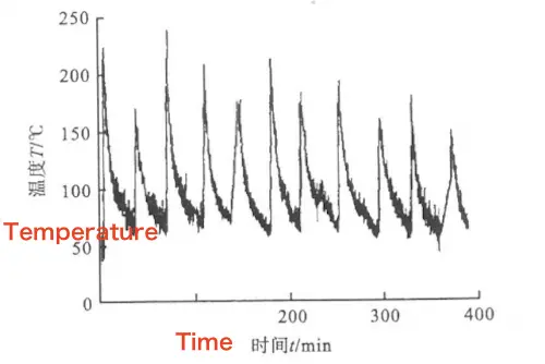
According to the temperature measurement results, the interpass temperature during valve body welding was controlled to remain below the safe operating limit of the valve seat sealing ring, which is 150 °C. This ensures that the sealing performance of the valve is not compromised.

Figure 1: Temperature change curve at 20 mm from the center of the weld seam
Welding was performed on a cylinder with an inner diameter of 600 mm and a wall thickness of approximately 50 mm. The ends of the cylinder were left unrestrained during welding. After welding, the measured deformation was approximately 2.5 mm in the axial direction and about 1.5 mm in the radial direction.
During the design phase of the fully welded ball valve, this welding deformation must be taken into account to ensure sealing performance. Accordingly, the clearance between the valve seat and the valve body should be adjusted. Air cooling or vibration techniques can be used during welding to reduce deformation. Typically, vibration welding results in the least deformation, followed by air cooling.

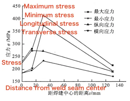
Figure 2: Residual stress distribution
Residual stress after welding was measured using the blind hole method (see Figure 2). The results showed that residual stress decreases as the distance from the center of the weld seam increases. A well-designed weld structure in the valve body can effectively reduce residual stress caused by deformation during welding. Additionally, the use of vibration or air cooling during welding can help reduce residual stress to varying degrees. In general, vibration welding is more effective at relieving residual stress after welding.
Post-weld inspection using X-ray and ultrasonic testing confirmed that the weld seams met all quality requirements. The mechanical property evaluations, including tensile, impact, and side bending tests, were also qualified. The heat-affected zone of the weld met the requirements specified in JB 4708.
By analyzing the factors that influence weld seam formation and weld seam metal properties, as well as evaluating the results of welding tests, the valve body structure, weld groove type, and valve seat design were optimized. The chemical composition of the valve body material was strictly controlled, and appropriate welding wire, flux, and process parameters were selected. Narrow-gap, multi-pass, and multi-layer welding was adopted, and the interlayer temperature was effectively controlled during the welding process. These measures fully meet the welding production requirements for fully welded ball valves.